ATX Power Supply Breakout Board
ATX power supplies are powerful, inexpensive, and easy to salvage from old desktop computers. This makes them a good choice for hobbyists who need tens of amps at +12V, +5V, or +3.3V. But it isn't easy to hook up one's project to the tangle of wires and plastic connectors coming out of the power supply. A common solution is to cut off the plastic connectors and solder directly to the wires; but this is irreversible and makes it difficult to quickly swap out a failing power supply.
A more elegant solution is to use a breakout board that mates with the plastic connectors and exposes the various rails as screw terminals. This is the approach taken by Dangerous Prototypes' ATX Breakout Board and several others. However, existing ATX breakout boards only use the single 24-pin motherboard connector and frequently also include 1.25A resettable polyfuses, which greatly limits the available power. I wanted to be able to make full use of a one-kilowatt power supply that I recently bought second-hand, so I developed my own ATX breakout board with a larger power capacity.
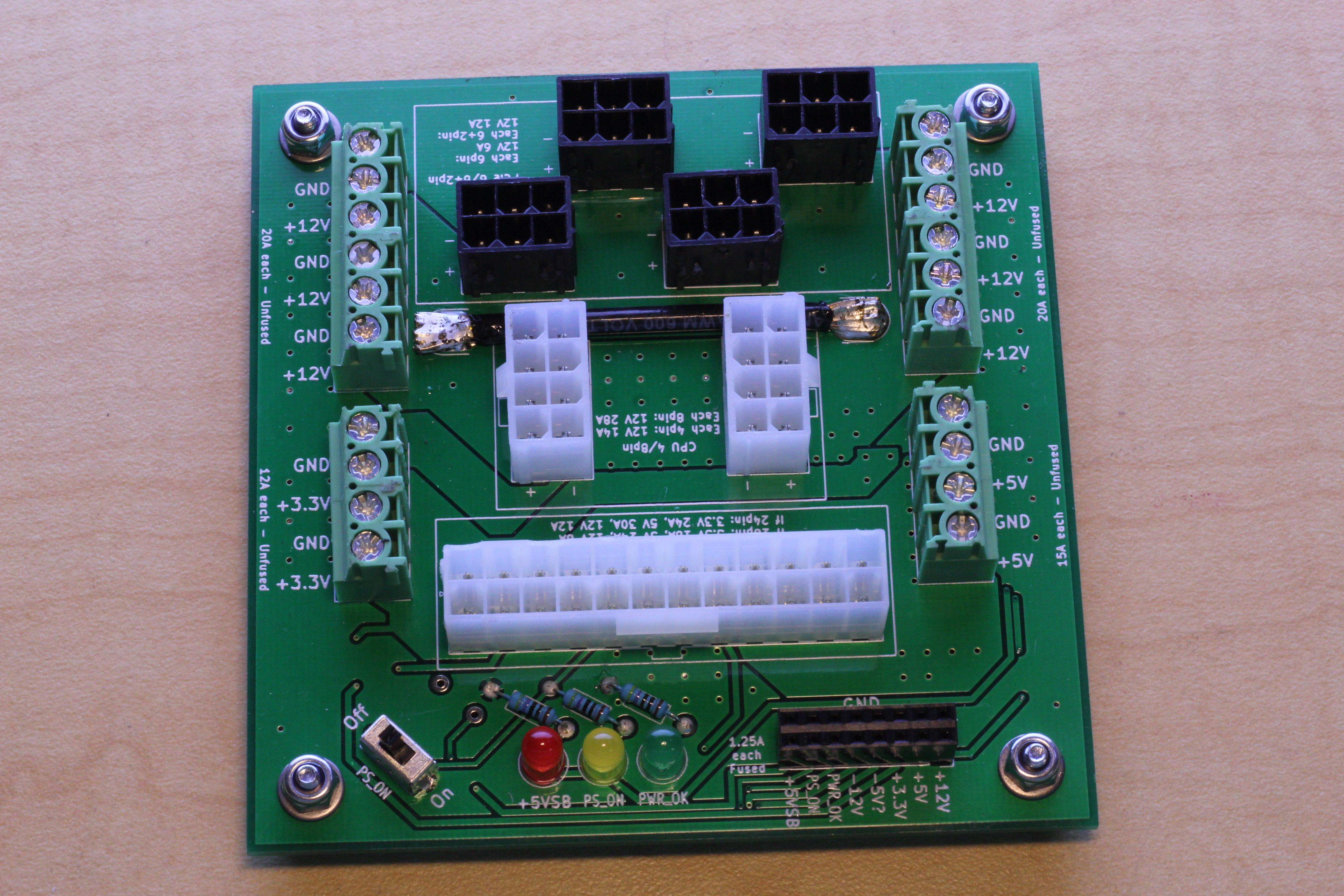
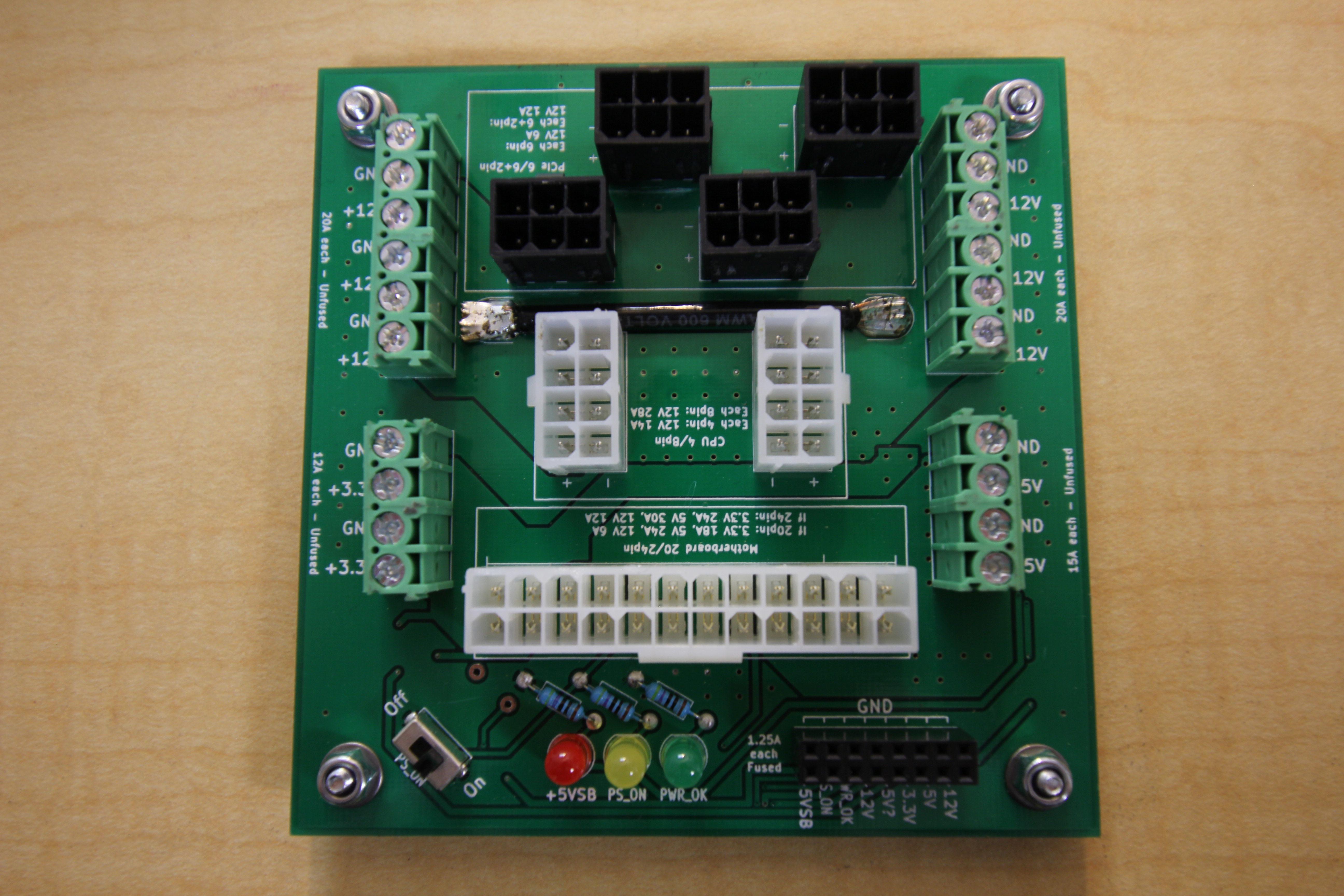
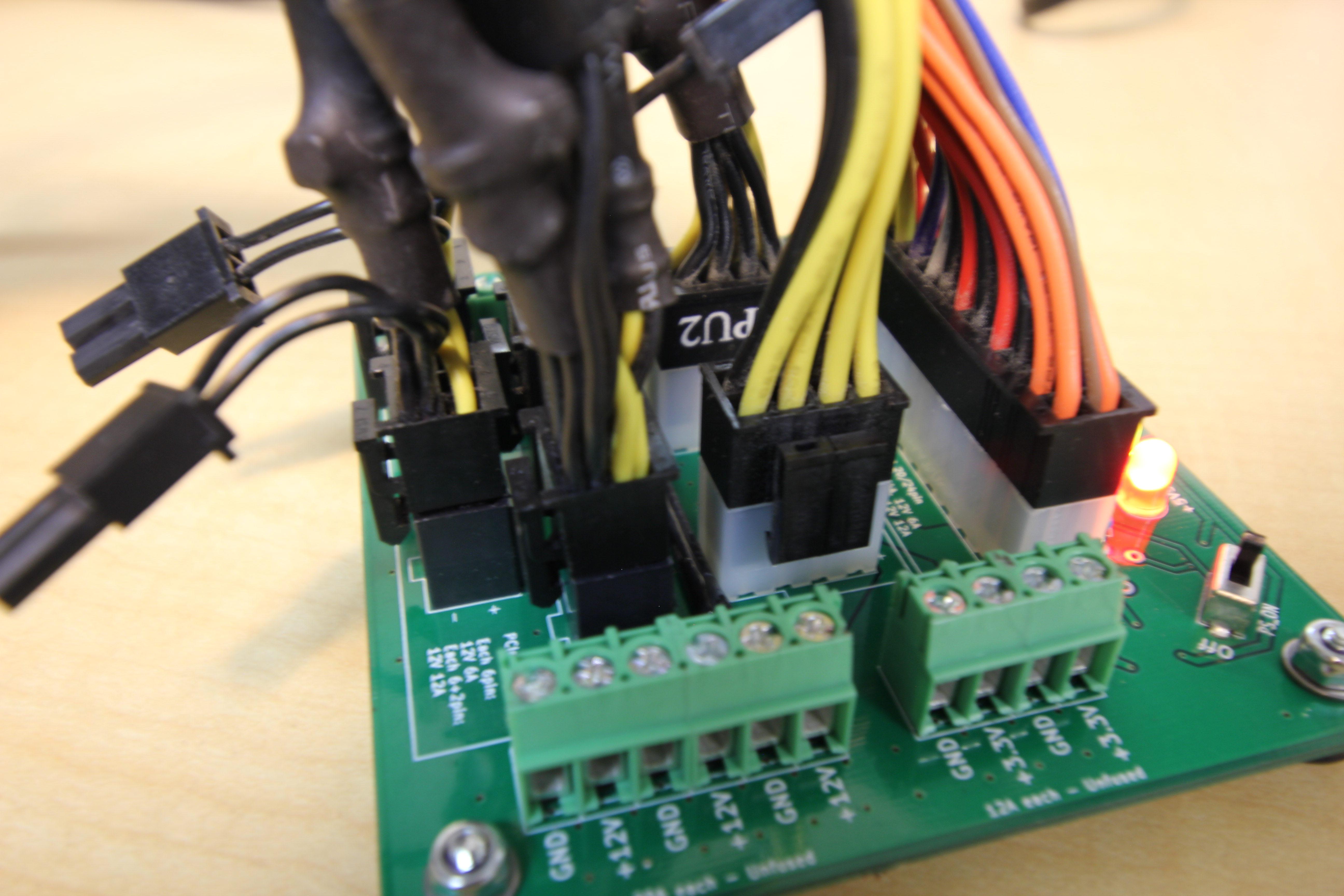
This breakout board plugs into the main 20-pin or 24-pin motherboard connector, up to two 4-pin or 8-pin EPS12V CPU power connectors, and up to four 6-pin or 6+2-pin PCIe connectors. When plugged into a sufficiently powerful power supply, it can provide up to 120A of +12V power, 30A of +5V power, and 24A of +3.3V power via two rows of screw terminals on the sides. An additional 16-pin female header provides power rails protected by 1.25V resettable polyfuses, including the -12V and optional -5V rails. An on-off switch and status lights make it easy to control the power supply; the control lines are also exposed via the 16-pin header so that the power supply can be controlled by a microcontroller if desired.
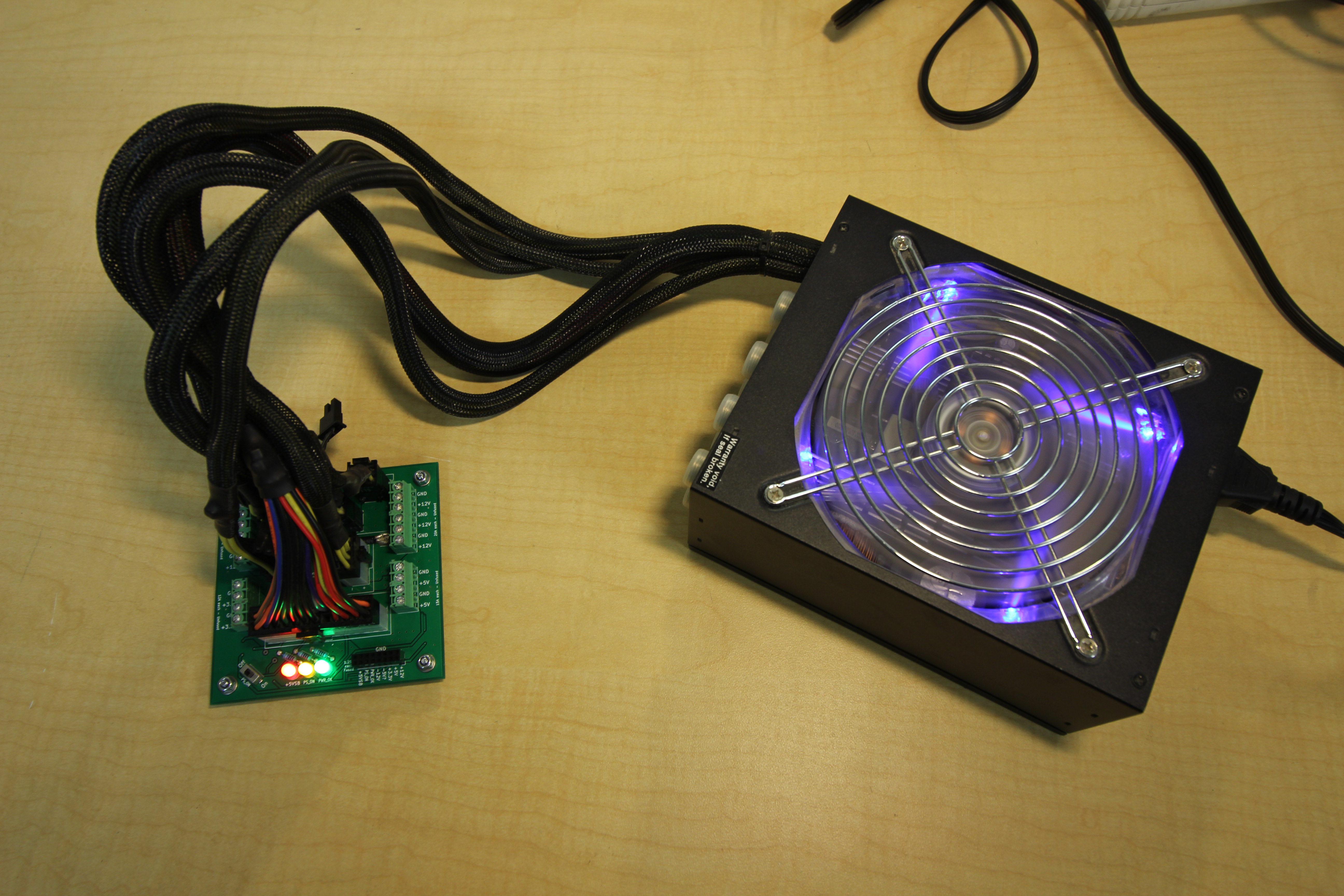
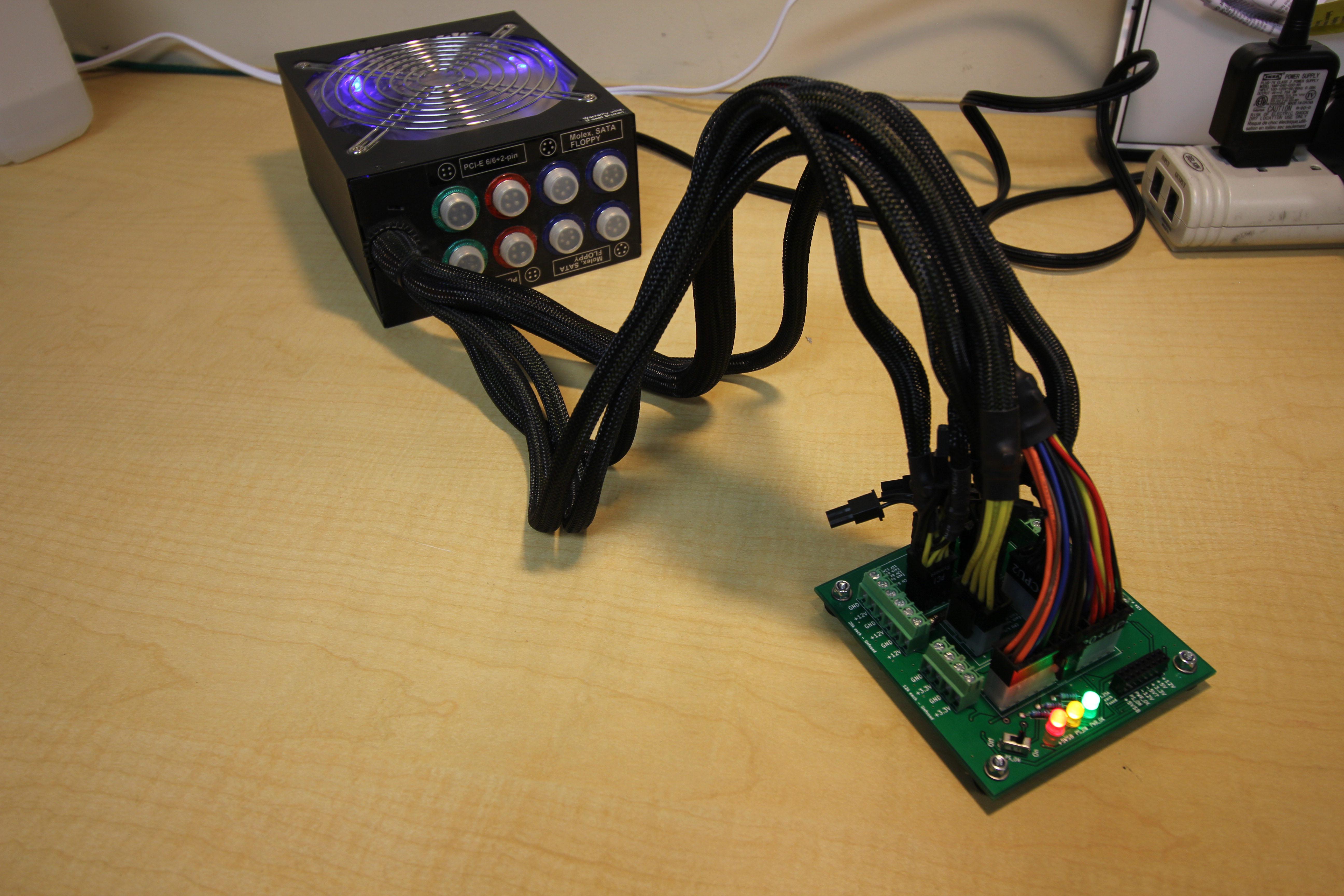
The board works beautifully. It can easily power twelve five-meter spools of LED lights, which together draw a total of 72A from the +12V rail:

Image gallery
Click images to view in high resolution.

Plans and Parts
The board is a 10cm by 10cm two-layer PCB using 1oz copper. I designed the board using KiCad and ordered the PCBs from Seeed Studio's PCB service; the PCBs cost about $20 plus about $5 for shipping for a batch of ten. The PCB designs are open-source, licensed under a Creative Commons Attribution-ShareAlike 2.0 Generic License. You can download them as a PDF schematic and Gerber files. The KiCad source files are also available (but beware, these are for KiCad 4.0.0 and will not work with newer versions).
The components required are as follows:
| Quantity | Description | Estimated Price |
|---|---|---|
| 1× | 24-pin Molex MiniFit Jr. header | $0.79 |
| 2× | 8-pin Molex MiniFit Jr. header | $1.20 each |
| 4× | 6-pin Molex MiniFit Jr. header (special PCIe variant!) | $0.93 each |
| 4× | Screw terminal (5mm spacing, 2 positions, interlocking) | $0.43 each |
| 4× | Screw terminal (5mm spacing, 3 positions, interlocking) | $0.66 each |
| 1× | Slide switch (SPDT) | $0.42 |
| 1× | Red LED (through-hole, 5mm) | $0.35 |
| 1× | Yellow LED (through-hole, 5mm) | $0.35 |
| 1× | Green LED (through-hole, 5mm) | $0.33 |
| 3× | Resistor (through-hole, 470Ω) | $0.10 each |
| 1× | 16-position female header (through-hole, 0.1in spacing) | $1.23 |
| 6× | Resettable polyfuse (1812 SMD package, 1.25A) | $0.18 each |
| 1× | Buffer IC (SOT-25 SMD package, non-inverting, enabled if pin 1 low) | $0.30 |
| 50cm | Copper wire (12AWG, stranded) | |
| 4× | Rubber foot | $0.28 each |
| 4× | Machine screw (#4 size) | |
| 4× | Nut (#4 size) |
The total cost for components is around $15-$20 per board when purchased from Digi-Key, plus shipping. Clicking this link will create a new Digi-Key cart containing the parts for the board (except for the hookup wire, machine screws, and nuts).
Design Notes
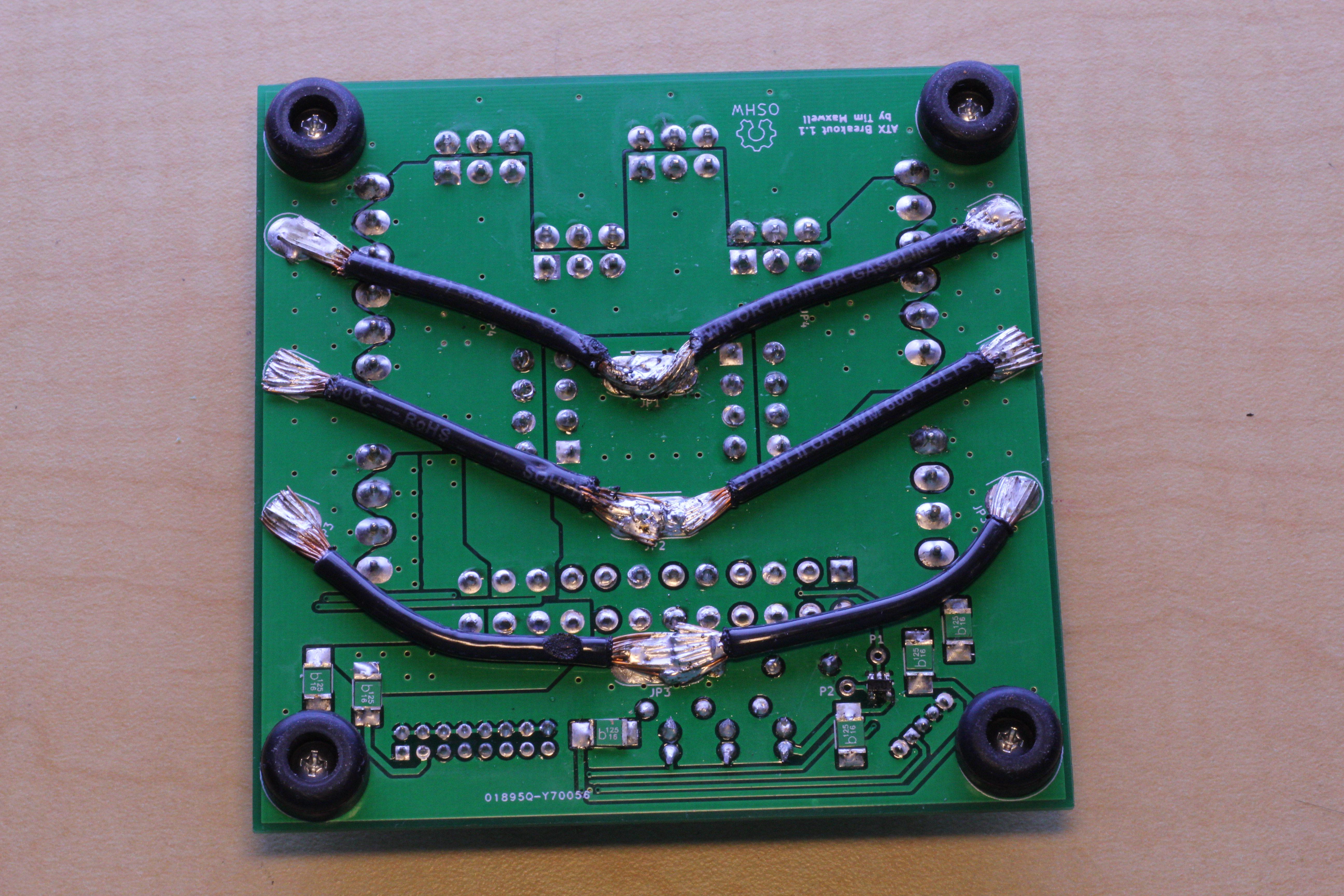
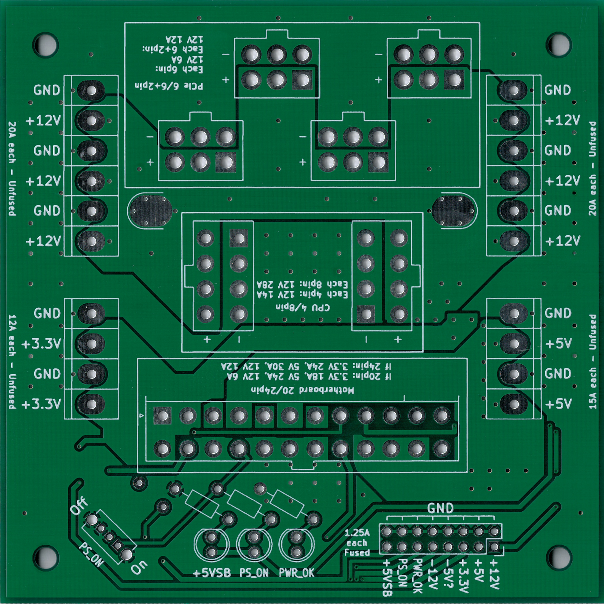
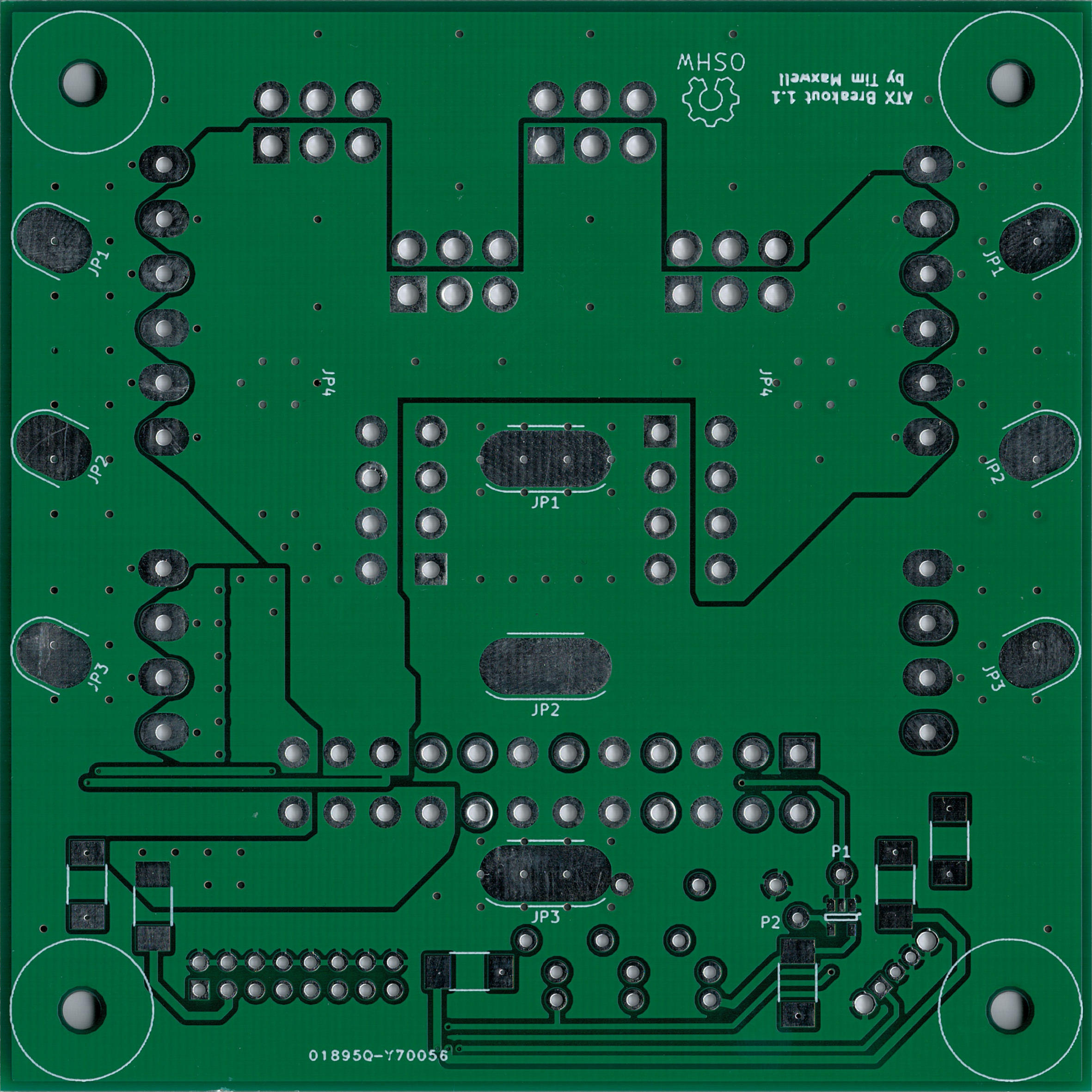
The main body of the circuit is quite simple; the power and ground rails from the Molex connectors are connected directly to the screw terminals along the sides. In order to achieve high current capacities, the main paths are large power planes. In addition, short pieces of 12AWG copper wire are soldered between the pads marked JP1-JP3 on the bottom (see image) and JP4 on the top to increase the capacity in places where the board copper alone might be inadequate. This makes some of the solder joints difficult, because the large power planes and fat copper wires tend to conduct heat away from the solder joints they are connected to. For some of the joints I found it necessary to use a 50-watt soldering iron dialed all the way up to 850°F. In the end the board didn't produce as much heat as I had feared, so it might be possible to redesign it to carry all the current in the board's copper without using the extra 12AWG wires.
The main three power rails are the +12V, +5V, and +3.3V rails. In addition, all ATX power supplies also provide a -12V rail and a +5V standby rail, and older power supplies provide a -5V rail. Only the three main rails are exposed via screw terminals, but all six rails are exposed via the 16-pin header, each with a 1.25A resettable polyfuse. Projects that don't need much power can use the fused rails to provide a measure of protection against short circuits.
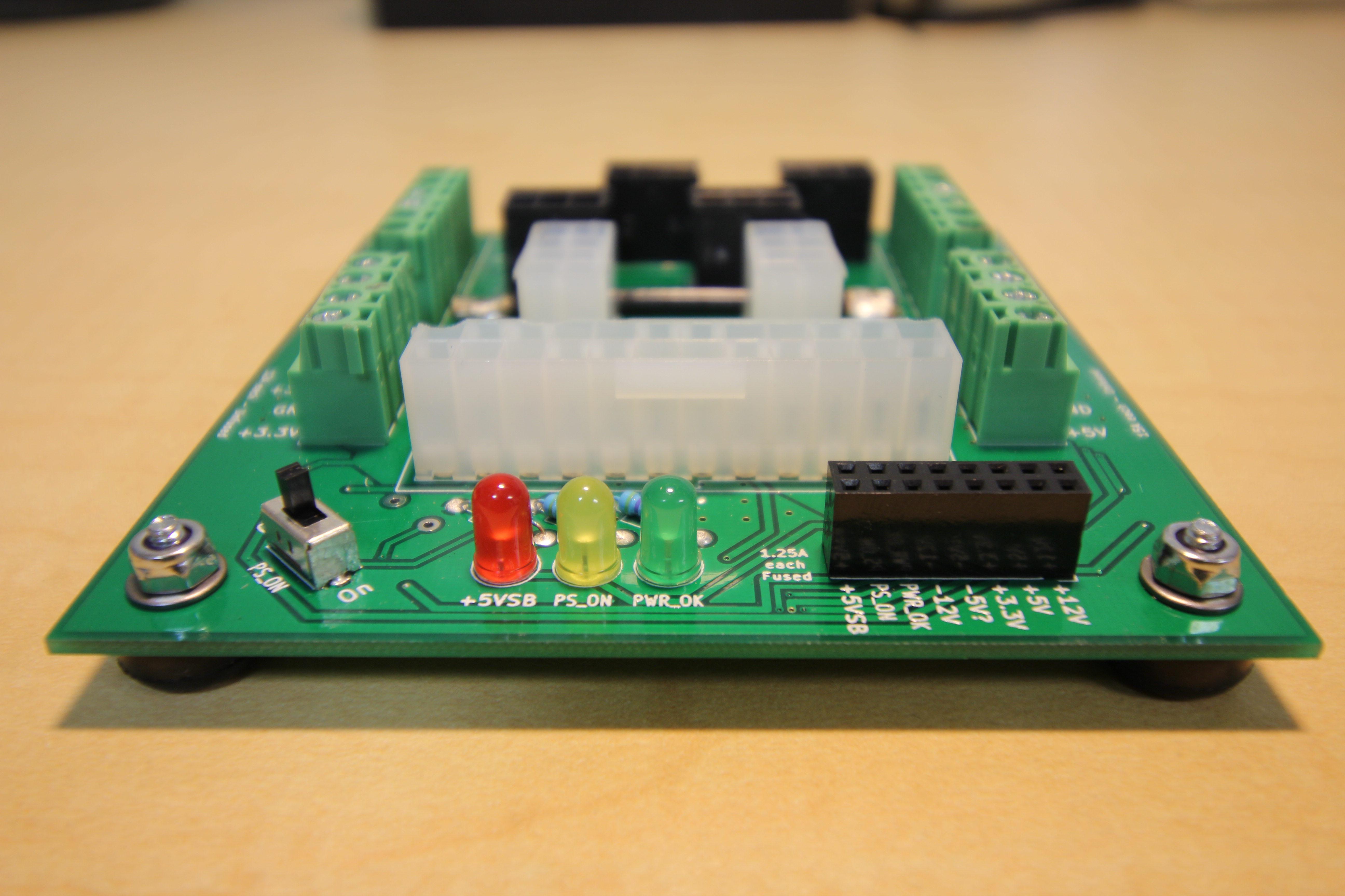
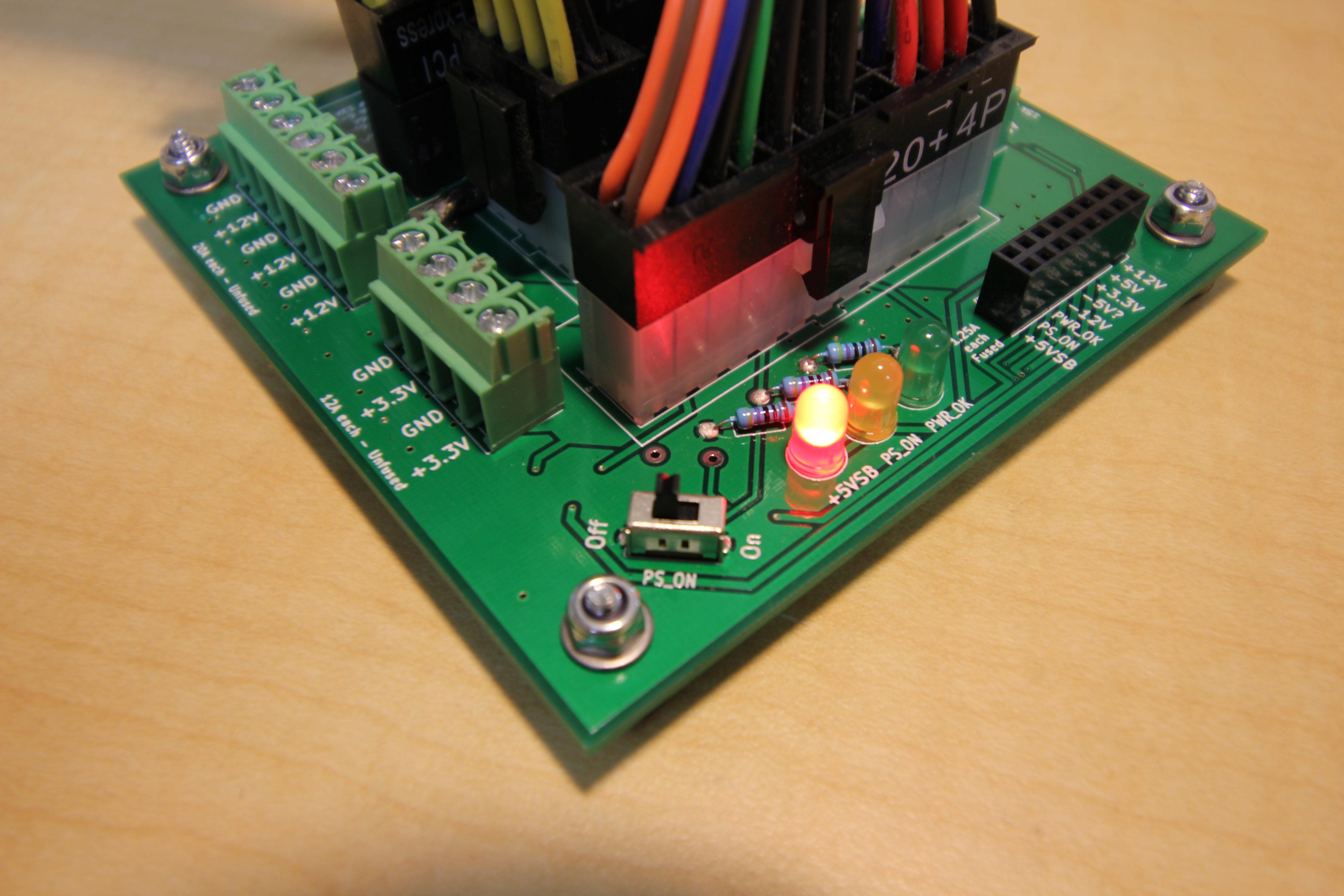
A red LED is powered from the +5V standby power rail so that it lights up whenever the power supply is plugged in. To turn on the power supply, the slide switch pulls the PS_ON control line low, which also causes the yellow LED to light up. The PS_ON control line could alternatively be pulled low via the 16-pin header, perhaps by a microcontroller or an external switch.
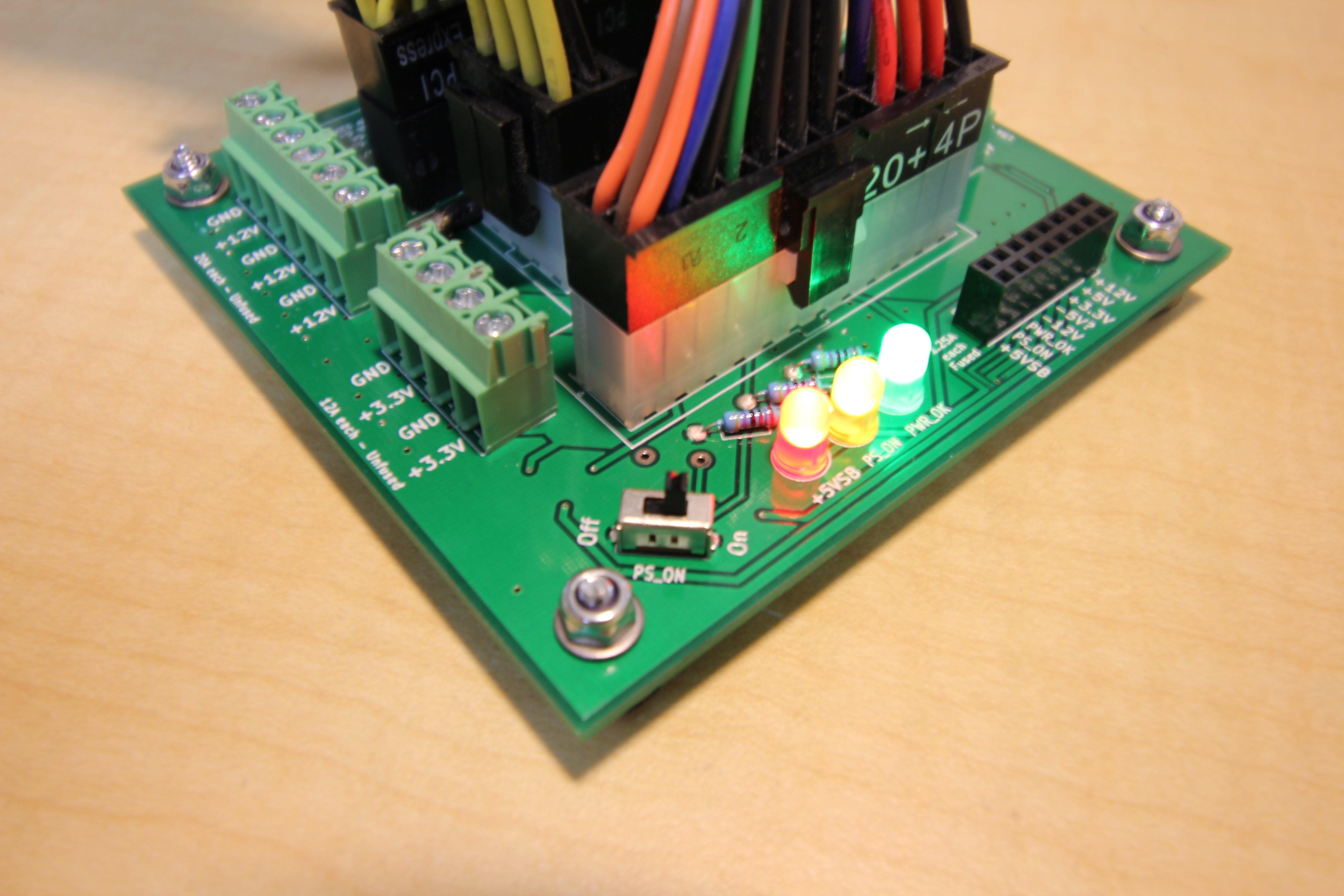
The PWR_OK line indicates when the power supply has completely turned on and all of the voltages are stable. The green LED lights up when the PWR_OK line is high. However, the PWR_OK line isn't ideal for driving an LED directly; the ATX power supply design guide prescribes that the high-state voltage on the PWR_OK line could be anywhere from 2.4V to 5.0V, the high-state impedance is 1kΩ, and it is only guaranteed to source 200µA. In practice most power supplies use a 5.0V high-state voltage and can supply plenty of current, but just to be safe the breakout board buffers the PWR_OK line using a 5V 8mA push-pull buffer IC. The buffer IC comes in a SOT-25 package, which some may find difficult to solder; if one is willing to take the risk of the PWR_OK LED not working correctly, the buffer IC can be omitted and instead a jumper can be installed between the pads marked P1 and P2. The PWR_OK signal that is exposed via the 16-pin header is the buffered signal; if for some reason one wants the original unbuffered signal straight from the power supply, it can be taken from the pad marked P1. Otherwise, the P1 and P2 pads can be left unconnected.
Some power supplies require a minimum load on the +5V rail in order to work properly, especially if there are substantial loads on the other rails. If this is a problem, the solution is to screw a couple of 10Ω 10W power resistors into the +5V screw terminal bank.
Some power supplies have multiple +12V rails. The breakout board ignores this and just connects all of the +12V lines together electrically. Normally this is not a problem, because most power supplies that advertise multiple +12V rails actually just have a single voltage regulator internally. But if the breakout board were connected to one of those rare power supplies with truly independent +12V rails, it could potentially damage the power supply. Do this at your own risk! See this detailed discussion for more information.
There is a mounting hole at each corner of the square. Each hole is 3.4mm in diameter and the centers are 85mm apart. I attached rubber feet to these holes so that the breakout board can sit on a desktop, but these could also be used to mount the board to something else if desired.